|

Brake and Clutch Instructions and Information
|
BRAKE PEDAL CONVERSION KIT INFORMATION AND INSTRUCTIONS This page is to clarify the "bolt in" statement in the Tilton hanging pedal assembly kit instructions from Tilton shown below. We want the customer to know the preparation that needs to be done before they can "bolt it in". As stated, no plumbing is provided. 105-115 HANGING PEDAL CARS 1971-1994.
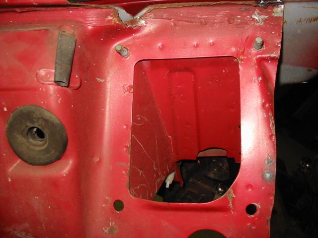
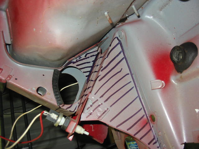
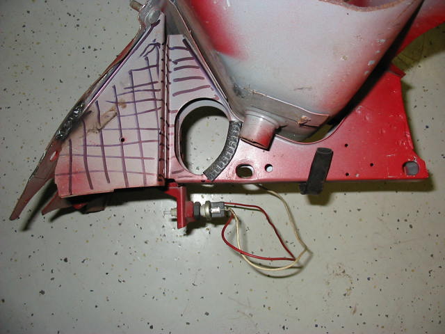
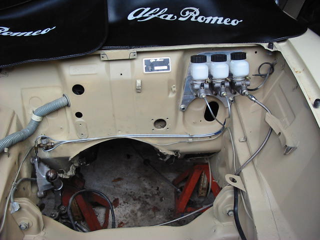
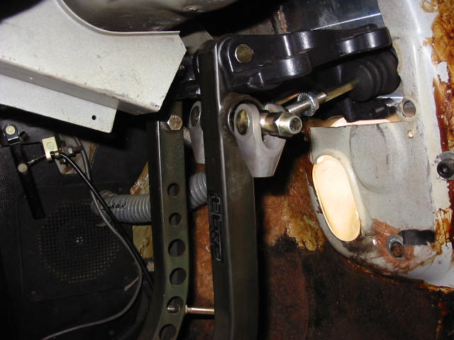
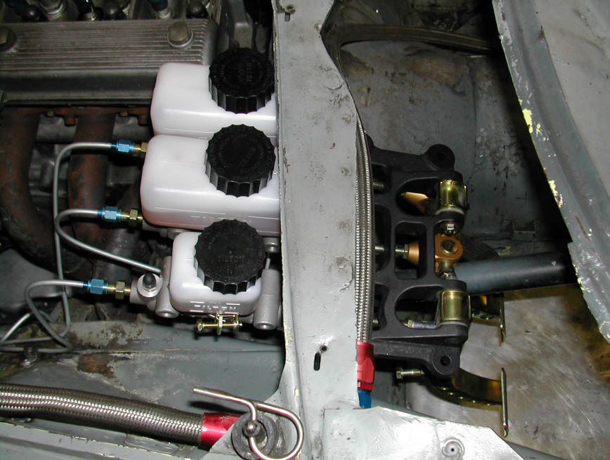
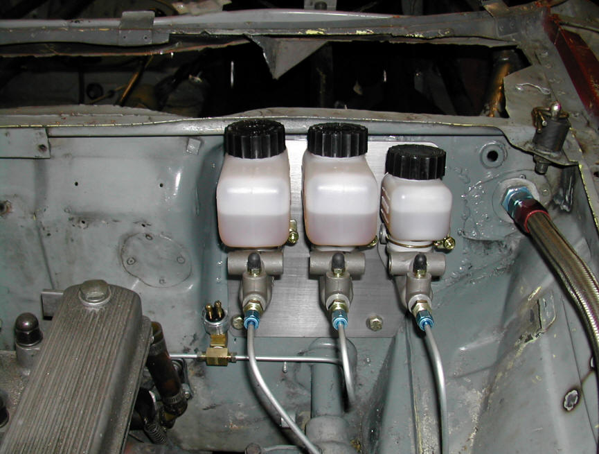
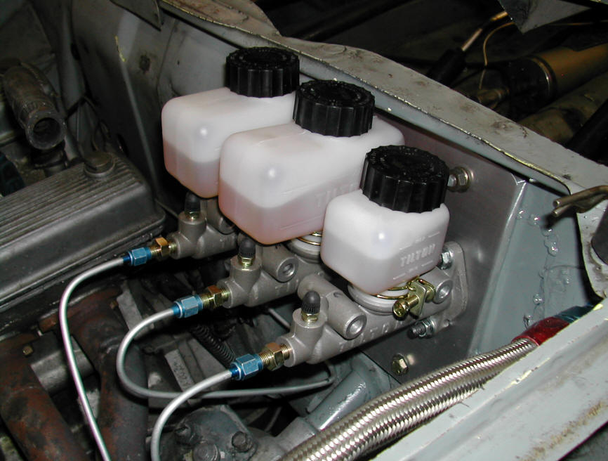
PREPARATION In each photo, the metal to be removed is marked. One cut away view is from the driver's left and one from the right. They both show the lower section of steering column bracket and stock pedal well that has to be removed to make room for the Tilton pedal assembly. This can be done in a matter of minutes with a die grinder zizz wheel or Sawzall. The good news is that the steering column mounting itself remains intact with the bracing and pocket on the firewall removed. Some customers have stated that this does not need reinforcement but we recommend that it should be reattached to the wiper well of the cowl above. There is only a quarter inch gap that will need to be bridged. This can be done by welding on a patch on each side or bolting in 1/4" pieces of metal sandwiched in the gaps. INSTALLATION With this preparation accomplished it is time to "bolt on" the aluminum adapter plate. The two 8mm upper holes in the plate go over the two original 8mm mounting studs. The two lower 8mm holes match the original and require two 8mm machine screws. Now it is time to mark the six 8mm master cylinder mounting holes and three cutouts. The 8mm holes can be drilled with the plate mounted. The cutouts need to be done with a 1 1/2" hole saw with the plate removed. Now install, or "bolt in", the plate, hanging pedal assembly and three master cylinders. With regard to the brake light switch, you will need to fabricate an extension bracket. The switch contact button can contact the square tube face of the brake pedal shaft. 105 EARLY MODEL FLOOR MOUNTED PEDAL CARS, 1965-1970 INSTALLATION Installation is different in that the four mounting holes for the aluminum adapter plate have to be drilled through the firewall and attachment is with four bolts. Position the mounting plate on the firewall and pencil the outline of the four firewall bolts (in each corner) on the firewall. Center-punch drill these four 8.5mm holes and install the plate with four 8mm bolts provided. Next, drill the three pairs (six 8.5mm) holes for the studs that mount the pedal assembly and master cylinders. With a 1.5 inch hole saw, cut the three 1˝ inch master cylinder holes, using the adapter as your template. The window left in the foot well by the removal of the floor pedal assembly can be covered with a rectangular metal plate and mounted with most of the original hardware. The brake light switch in these cars is a pressure switch located in the front brake line. No plumbing is provided with this kit. Always use solid metal line for the brakes. The clutch can be adapted to the original line to the slave cylinder. However it is a great idea to install new Aeroquip with a dry break quick disconnect in line near the slave cylinder. This makes gearbox or engine removal a piece of cake with no more hydraulic fluid mess and no need to bleed the clutch. It will save at least a half hour of labor each R&R and pay for this upgrade in a couple of hours. See installed unit in Bias Bar Section below... This is a finished installation of our Tilton Hanging Pedal Brake Kit with the optional Plumbing Package in a 67 Duetto.
|
|
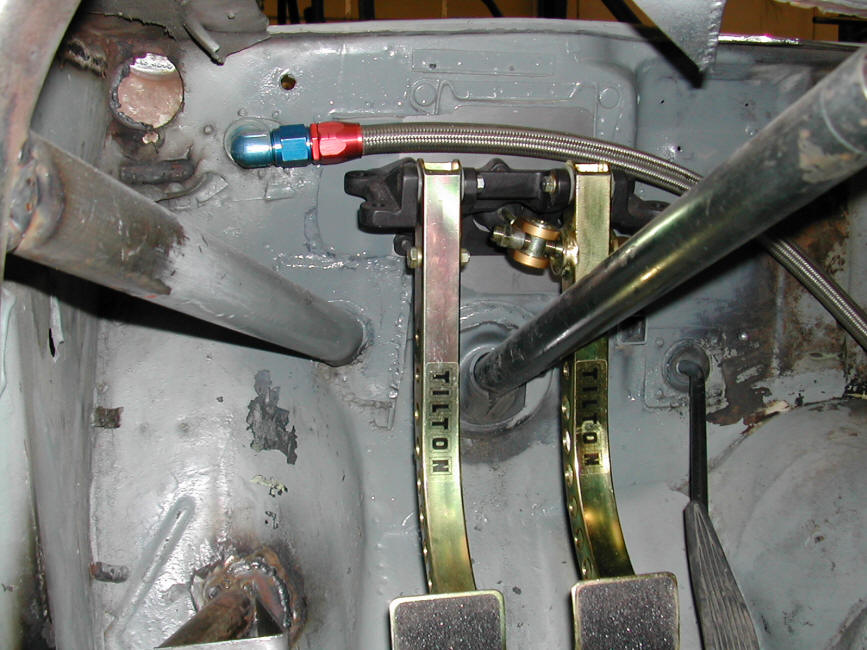
Typical MC/Bias bar/Pedal installation in a
fendered car - top mounted pedals (Click for full size images)
|